The aim of the project is to avoid accidents by controlling the speed of vehicles automatically.
Problem statement
Automatic vehicle speed control system to enhance road safety and improve fuel efficiency. This system should be capable of monitoring and controlling the speed of a vehicle in real-time, taking into account various factors such as road conditions, speed limits, and traffic density. The goal is to reduce the likelihood of accidents, minimize speeding violations, and optimize fuel consumption while ensuring a smooth and comfortable driving experience for the occupants.
Material used
Input: Ultrasonic sensor Brain: TinkerSpace Brain Board Output: DM Motor + Motor driver Battery: 5V Lithium-ion rechargeable battery
Component description
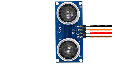
Ultrasonic sensor
The function of Ultrasonic sensor is to detect the object and send the signal to the Brain unit (TinkerSpace board).
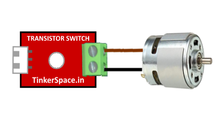
DC Motor
The function of the DC Motor is to
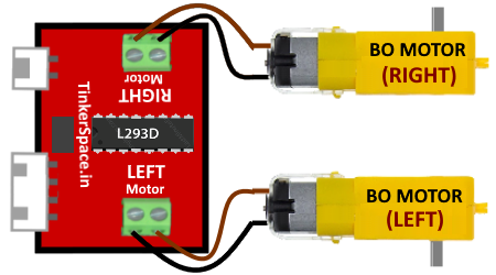
Motor driver
The function of the Motor Driver is
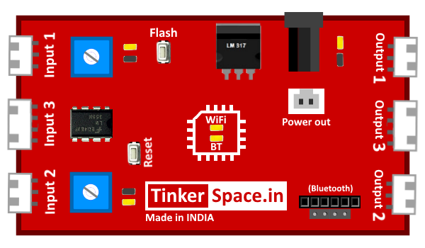
TinkerSpace Brain Board
TinkerSpace board acts as brain of this project, its function is to monitor Ultranisoc Sensor and control the DC Motor and Motor Driver.
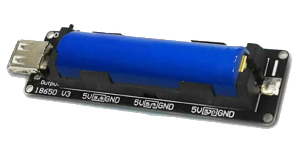
Battery
5V Lithium-Ion battery is used to power-up this project
Working description
Case 1: when Ultrasonic Sensor detects the object within the range of 10cm input sends a signal to the Tinkerspace brain board. The brain board automatically turns of the vehicle
Case 2: when Ultrasonic Sensor detects the object within the range of 10cm to 30 cm input sends a signal to the Tinkerspace brain board. The brain board automatically slow down the vehicle speed
Case 3: when Ultrasonic Sensor detects the object with the range of above 30cm input sends a signal to the Tinkerspace brain board. Automatically vechile speed will come to normal speed
Circuit Design (DesignSpace)
Step 1: Open TCode App -> Create New project -> Open DesignSpace
Step 2: Connect the Ultrasonic Sensor to INPUT 3 of the Brain board.
Step 3: Connect DC Motor to Output 1 and Motor Driver to Output 3 of the Brain Board.