The aim of the project is to Control lighting, and feeding schedules in a chicken coop
Problem statement
The system should include features like automated feeding, egg collection, and predator detection to enhance poultry management efficiency. The goal is to create a smart, user-friendly solution that optimizes chicken welfare, ensures egg production, and minimizes manual labor for farmers.
Material used
Input: Light Sensor and Timer Brain: TinkerSpace Brain Board Output: 2 Servo Motor and Display Battery: 5V Lithium-ion rechargeable battery
Component description
Light sensor
The function of light sensor is to detect the light and send the signal to the Brain unit (TinkerSpace board).
Timer
Timer is used to feed the chicken in a specific time and to show the time in display.
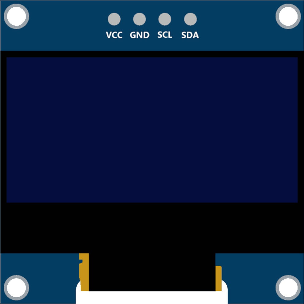
Display
Display is used to show the time.
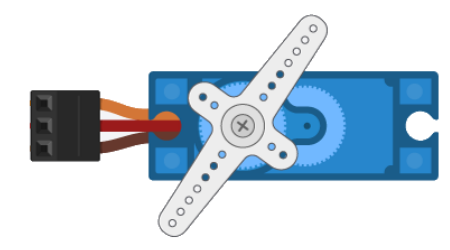
2 Servo Motor
Servo Motor 1:The first servo motor is used to open and close the window to maintain the appropriate light required for the coop.
Servo Motor 2:The other servo motor is used to feed the chicken in a specific time.
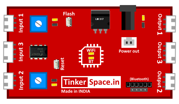
TinkerSpace Brain Board
TinkerSpace board acts as brain of this project, its function is to monitor Timer and Light Sensors and control the Display and Servo Motor.
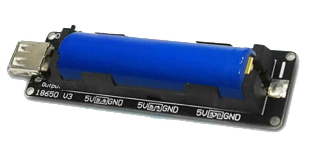
Battery
5V Lithium-Ion battery is used to power-up this project
Working description
Case 1: When the light is more, light sensor turns ON and sends the signal to the brain board. The brain board oscilates the servo motor to 60 Degree(Window closes partially). Case 2:When the light is less, light sensor turns OFF and sends the signal to the brain board. The brain board oscilates the servo motor to 0 Degree(Window opens partially). Case 3:When the timer shows the time 10:00 , The brain board oscillates the servo motor to release the food.
Case 4: When the timer shows the time 3:00 , The brain board oscillates the servo motor to release the food.
Case 5: When the timer is ON, the brain board sends the signal to the Display to Show time.
Circuit Design (DesignSpace)
Step 1: Connect LIGHT SENSOR input 1 and Timer to input 2
Step 2:Connect SERVO MOTORs to output 1 and output 2 and Display to output 3