The aim of the project is to Implement a system that adjusts the position of potted plants to ensure they receive optimal sunlight using a light sensor and a servo motor.
Problem statement
The system should provide real-time data on light intensity, duration, and optimal positioning to ensure that plants receive adequate sunlight for healthy growth. Address challenges such as accurate light measurement, adaptability to different plant species, and user-friendly interfaces for plant enthusiasts. Create a sunlight tracker solution that helps optimize indoor plant care, promoting efficient use of natural light and contributing to the well-being of indoor plants.
The function of light sensor is to detect the light and send the signal to the Brain unit (TinkerSpace board).
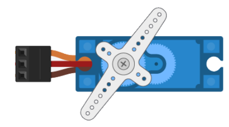
Servo Motor
Servo motor is used to track the movement of the sun and rotate in a same diraction where sun is detected
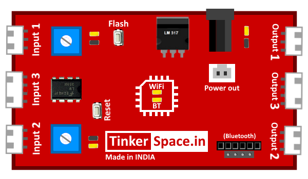
TinkerSpace Brain Board
TinkerSpace board acts as brain of this project, its function is to monitor Light Sensors and control LED LAMP, Servo Motor.
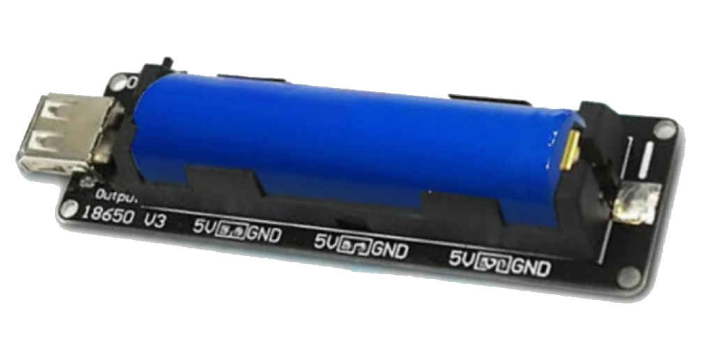
Battery
5V Lithium-Ion battery is used to power-up this project
Working description
Case 1: When the light is detected in left, left light sensor turns ON and sends the signal to the brain board. The brain board oscilates servo motor to 0Degree .
Case 2: When the light is detected in right, right light sensor turns ON and sends the signal to the brain board. The brain board oscilates servo motor to 180Degree
Case 3: When the light is detected in both sides, both light sensor turns ON and sends the signal to the brain board. The brain board oscilates servo motor to 90Degree.
Case 4: When no light is detected in both sides, both light sensor turns OFF and sends the signal to the brain board. The brain board oscilates servo motor to 90Degree .
Circuit Design (DesignSpace)
Step 1: Connect LIGHT SENOSOR to input 1 and input 2