To switch water to multiple agricultural land with equal intervals of time
Problem statement
The system should include programmable timers for automated watering schedules based on crop requirements and local weather conditions. Explore the integration of soil moisture sensors to ensure precise and efficient water usage, minimizing wastage and promoting water conservation. Consider developing a user-friendly interface, possibly through a mobile app or control panel, allowing farmers to customize watering schedules and monitor system performance remotely. The goal is to create an intelligent and efficient irrigation solution that enhances crop yield while minimizing water usage in agriculture
Material used
Input: Timer Brain: TinkerSpace Brain Board Output: Servo motor and Transistor switch with Water Pump Battery: 5V Lithium-ion rechargeable battery
Component description
Timer
The function of Timer is to set the time
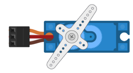
Servo Motor
Servo motor is used to change the direction of water.
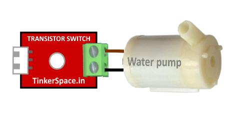
Transistor Switch + Water Pump
Transistor switch is used to control the water pump.
Water pump is used to put water for plant.
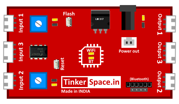
TinkerSpace Brain Board
TinkerSpace board acts as brain of this project, its function is tis to monitor Timer and Servo motor,Transistor switch,Water pump.
Battery
5V Lithium-Ion battery is used to power-up this project
Working description
Case 1: When the Timer is set to 10.00am,The brain board sends the signal to Water pump to ON it and Servo motor oscilates to 0 Degree.
Case 2: When the Timer is set to 10.10am,The brain board sends the signal to Water pump to ON it and Servo motor oscilates to 90 Degree.
Case 3: When the Timer is set to 10.20am,The brain board sends the signal to Water pump to ON it and Servo motor oscilates to 180 Degree.
Case 4: When the Timer is set to 10.30am,The brain board sends the signal to Water pump to OFF it and Servo motor oscilates to 0 Degree.
Case 5: When the Timer is set to 2.00am,The brain board sends the signal to Water pump to ON it and Servo motor oscilates to 0 Degree.
Case 6: When the Timer is set to 2.10am,The brain board sends the signal to Water pump to ON it and Servo motor oscilates to 90 Degree.
Case 7: When the Timer is set to 2.20am,The brain board sends the signal to Water pump to ON it and Servo motor oscilates to 180 Degree.
Case 8: When the Timer is set to 2.30am,The brain board sends the signal to Water pump to OFF it and Servo motor oscilates to 0 Degree.
Case 9: When the Timer is set to 7.00am,The brain board sends the signal to Water pump to ON it and Servo motor oscilates to 0 Degree.
Case 10: When the Timer is set to 7.10am,The brain board sends the signal to Water pump to ON it and Servo motor oscilates to 90 Degree.
Case 11: When the Timer is set to 7.20am,The brain board sends the signal to Water pump to ON it and Servo motor oscilates to 180 Degree.
Case 12: When the Timer is set to 7.30am,The brain board sends the signal to Water pump to OFF it and Servo motor oscilates to 0 Degree.
Circuit Design (DesignSpace)
Step 1:Connect SERVO MOTOR to output 1 and TRANSISTOR SWITCH(WATER PUMP) to output2