The aim of the project is to Design a helmet with built-in indicators, brake lights
Problem statement
The smart helmet should include functionalities such as built-in communication systems, heads-up display for navigation, real-time monitoring of vital signs, and automatic emergency response capabilities. Design the helmet to be comfortable, durable, and aesthetically pleasing while addressing the challenges of integrating technology without compromising on safety standards. Consider factors like connectivity, user interface simplicity, and energy efficiency in developing a comprehensive solution for motorcyclist safety and convenience.
Material used
Input: 2 Push Button Brain: TinkerSpace Brain Board Output: 2 Red LED Battery: 5V Lithium-ion rechargeable battery
Component description
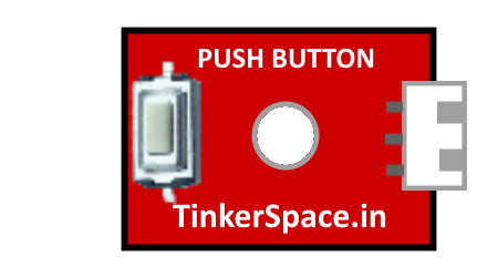
2 Push Button
Push button 1 : Push button 1 is located on the left side of the handle.
Push button 2 : Push button 2 is located on the right side of the handle.
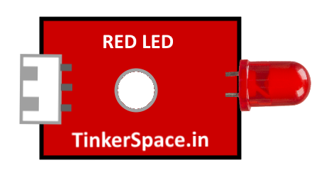
2 Red LED
RED LED 1: RED LED 1 is used to indicate left if left side button is pressed
RED LED 2: RED LED 2 is used to indicate right if Right side button is pressed
Note: If both buttons are pressed it will indicate break light
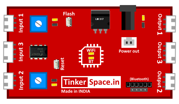
TinkerSpace Brain Board
TinkerSpace board acts as brain of this project, its function is to monitor 2 Push Button and control the Red LED
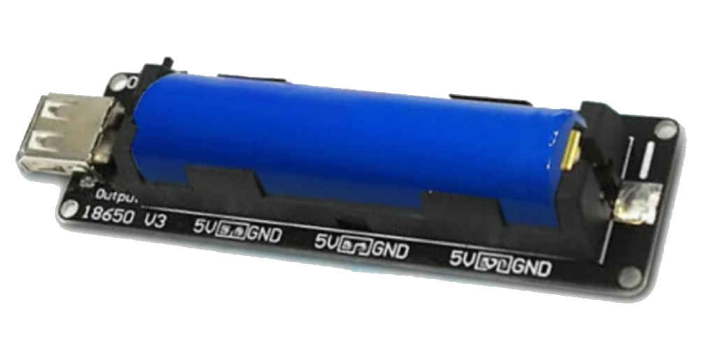
Battery
5V Lithium-Ion battery is used to power-up this project
Working description
Case 1: When the left push button is pressed, The brain board sends the signal and turns on the left RED LED to 100%.
Case 2: When the left push button is not pressed, The brain board sends the signal and turns on the left RED LED to 0%.
Case 3: When the right push button is pressed, The brain board sends the signal and turns on the right RED LED to 100%.
Case 4: When the right push button is not pressed, The brain board sends the signal and turns on the right RED LED to 0%.
Case 5 : When the both push button is pressed, The brain board sends the signal and turns on both RED LED to 100%.
Case 6: When the both push button is pressed, The brain board sends the signal and turns on both RED LED to 0%.
Circuit Design (DesignSpace)
Step 1: Connect 2 PUSH BUTTONS to input 1 and input 2