The aim of the project is to Develop a small solar-powered display that rotates to follow the sunlight, showcasing information or artwork.
Problem statement
The system should be capable of providing clear visibility in varying light conditions and should incorporate energy-efficient technologies for extended operation, even in low-light environments. Consider challenges such as effective energy storage, durability, and adaptability to different display sizes and types. Create a solar-powered display solution suitable for outdoor applications, such as public transportation stops, informational kiosks, or remote areas where traditional power sources are limited.
Material used
Input: 2 Light Sensor Brain: TinkerSpace Brain Board Output: LED LAMP and Servo Motor Battery: 5V Lithium-ion rechargeable battery
Component description
2 Light sensor
The function of light sensor is to detect the light and send the signal to the Brain unit (TinkerSpace board).
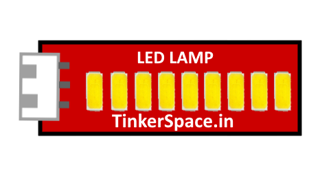
LED LAMP
LED lamp is used when
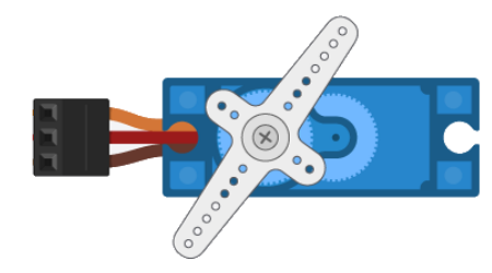
Servo Motor
Servo motor is used to track the movement of the sun and rotate in a same diraction where sun is detected
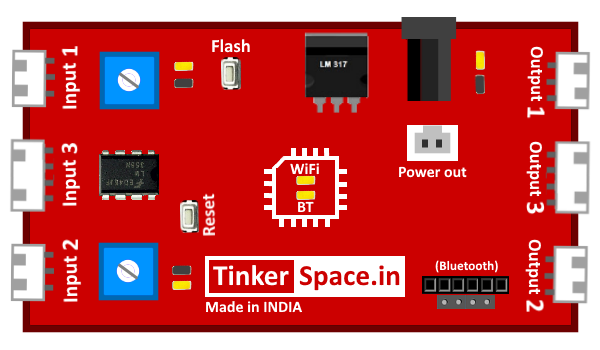
TinkerSpace Brain Board
TinkerSpace board acts as brain of this project, its function is to monitor Light Sensors and control LED LAMP, Servo Motor.
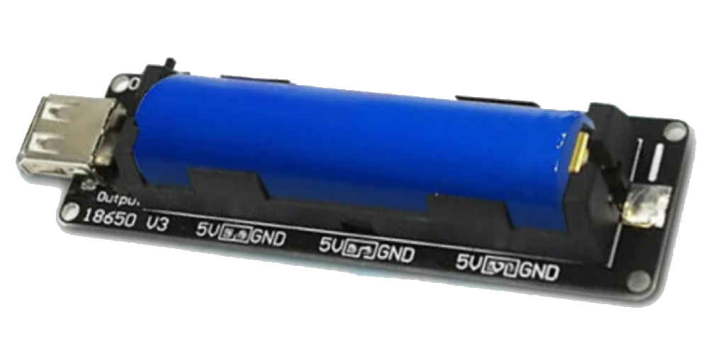
Battery
5V Lithium-Ion battery is used to power-up this project
Working description
Case 1: When the light is detected in left, left light sensor turns ON and sends the signal to the brain board. The brain board oscilates servo motor to 0Degree and turns on the LED Lamp to 0% .
Case 2: When the light is detected in right, right light sensor turns ON and sends the signal to the brain board. The brain board oscilates servo motor to 180Degree and turns on the LED Lamp to 0% .
Case 3: When the light is detected in both sides, both light sensor turns ON and sends the signal to the brain board. The brain board oscilates servo motor to 90Degree and turns on the LED Lamp to 0% .
Case 4: When no light is detected in both sides, both light sensor turns OFF and sends the signal to the brain board. The brain board oscilates servo motor to 90Degree and turns on the LED Lamp to 100% .
Circuit Design (DesignSpace)
Step 1: Connect LIGHT SENOSOR to input 1 and input 2
Step 2:Connect LED LAMP to output 1 and Servo Motor to output 2